Use of Table of Steel Section Properties
Different steel rolling mills provide section properties of the rolled section they manufacture.The provided section properties are aimed to save time in calculating them. These section properties used directly in the structural designs. This article will answer questions like, What are the properties of steel sections and their uses? Explanation will be provided in simple language so that the people with limited knowledge can also get benefit from this article. Engineering students and those who want to learn structural engineering will get benefit from this article.
Different standard steel sections are available in the market. Some basic common steel sections that are manufactured by rolling mills are summarised below:
 |
| Basic Steel Sections |
For each section the necessary section properties are available in the section properties tables. The basic section properties that are provided by the rolling mills are as follow:
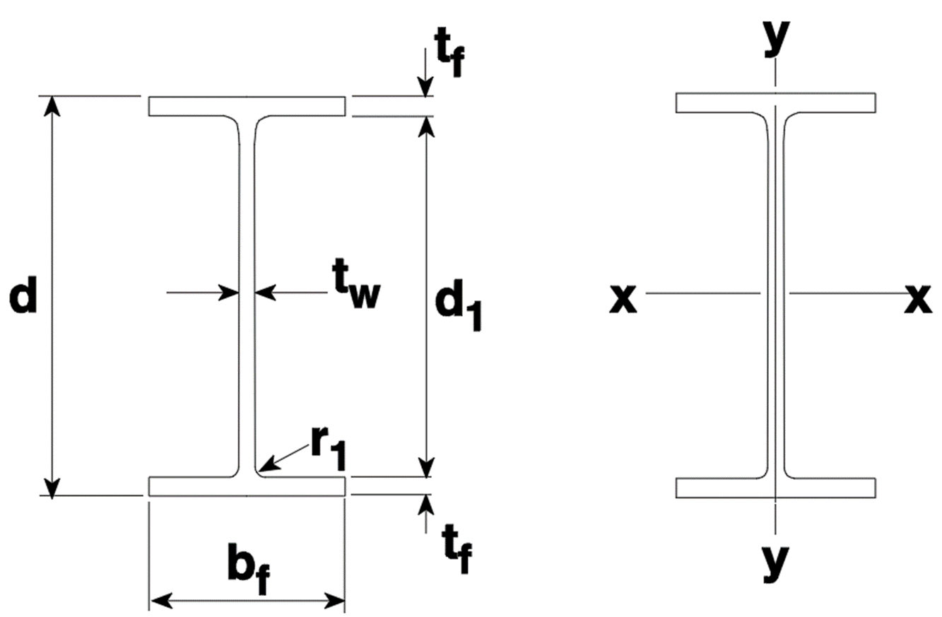
Minimum yield (fy) and Tensile (fu) stresses, Mass of section per unit length, Distance of Centre of Gravity (Cx, Cy), Designation (name of section), Depth of Section (d), Flange width (bf), Flange Thickness (tf), Web thickness (tw), Root Radius (r1), Depth Between Flanges (d1), Gross Area of Cross Section (Ag), Moment of Inertia about major (Ix) and minor axis (Iy), Section modulus about major (Zx) and minor axis (Zy), Radius of gyration about major (rx) and minor axis (ry), Torsion constant (J), etc.
For example, following I-Section shows its different dimensions.
 |
| Basic dimensions of I-Section |
Similarly, depending on section types, more necessary section dimensions and properties are also provided by the rolling mills. In order to use the section properties table for designing a beam, we need to understand basically the following properties.
Section modulus, Z= I/(d/2) or Zx=Ix/(d/2), Zy=Iy/(bf/2).
Here d/2 and bf/2 are the distances of Centre of Gravity from the extreme fire measured along y and x axes respectively. Similarly, in this I-section the Ix and Iy are the major and minor axis moment of Inertias respectively.
As we know, Force= Stress x Cross section area, F=σ.A
Similarly, Moment=Stress x Section modulus, M=σ.Z or Mx=σ.Zx, My=σ.Zy
Expression on the right hand side of the equality needs to be multiplied by a necessary capacity reduction factor to obtain the related capacity.
Radius of Gyration, r = (I/A)^0.5 or rx = (Ix/A)^0.5, ry = (Iy/A)^0.5
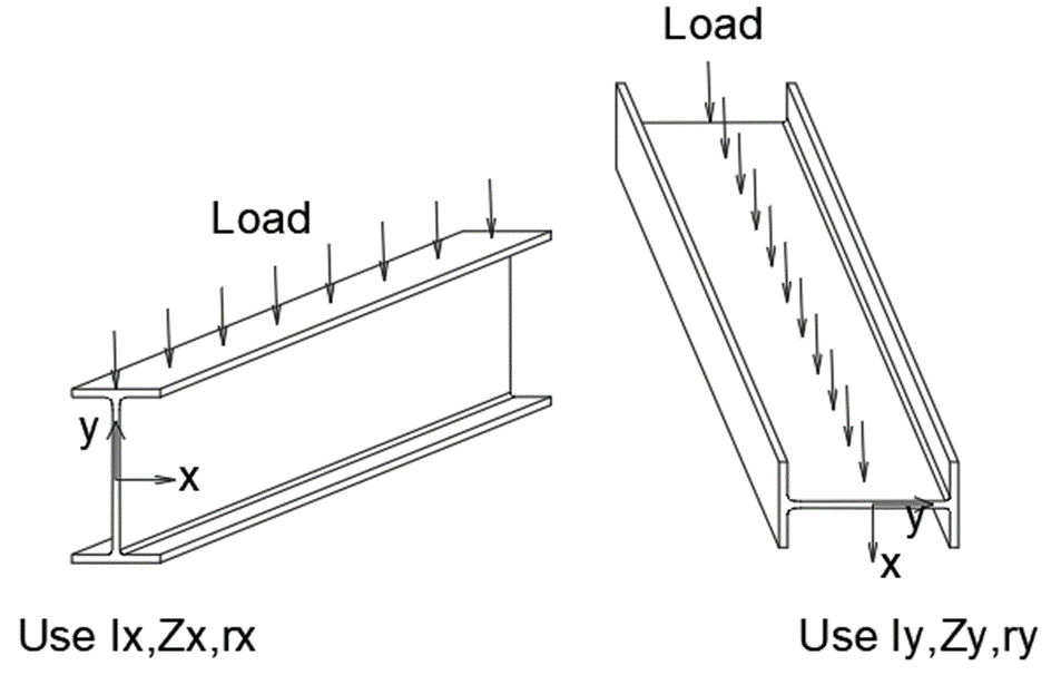
Following figures demonstrate briefly how different section properties related to major and minor axis are used in the design of beams depending on its orientation.
 |
| Use of section properties according to orientation of the section |
Let's see a quick example of using the section properties in the design of a beam with full lateral restraints.
Example-1 Beam loaded in the direction of axis-y
Factored applied maximum Bending Moment, Mx*=90 kNm
Let's assume the section modulus obtained from the section properties table, Zx=354x10^3 mm3 and
Yield stress, fy = σ = 320 N/mm2
Associated bending capacity of the beam, фMx=ф.σ.Zx =0.9*320*354000
=101952000 Nmm = 101.95 kNm > 90 kNm
Size of the beam is adequate for the bending moment
Example-2 Beam loaded in the direction of axis-x
Factored applied max Bending Moment, My*=15 kNm
Let's assume the section modulus obtained from the section properties table, Zy=61.2x10^3 mm3 and
Yield stress, fy = σ = 320 N/mm2
Associated bending capacity of the beam, фMy=ф.σ.Zy =0.9*320*61200
=17625600 Nmm = 17.62 kNm > 15 kNm
Size of the beam is adequate for the bending moment
Similarly, different other design parameters, such as shear capacity, deflection, etc., shall be checked using the data available in the same table of section properties.
With this example we can see that the beam major axis has greater bending capacity than the minor axis.
Table of steel section properties contains most of the section properties that are required to calculate different section and member capacities of the standard sections, such as, Tension, Compression and Torsion capacities. Nowadays, most of the rolling mills provide different section and member capacities of their steel sections. Such tables really save calculation time of Structural Engineers. Additionally, most of the structural analysis software also check/design member completely.
In the
next article I will explain briefly about arrangement of bolted connections in steel structures.
article: Design of members with combined actions


Comments